Furnaces
The correct engineering of a furnace is the key to realize a system that is, at the same time, flexible and efficient.
Find out the general design criteria guiding us in the engineering of a furnace, and the 3 steps that we actually follow.
General design criteria
There are two reasons for starting any project in energy from waste or biomass energy from a careful examination of the materials to be used as fuel.
The first reason is that waste and biomass characteristics do change – even significantly – over time.
The second is originated by the requirement to process materials that, while “poor” in terms of their energy content, can be available at a lower price or at zero cost; or by the need to process over the year different biomasses, whose availability is only seasonal.
The stabilization of fumes flow:
- improves the functioning of the flue gas cleaning system
- minimizes the possibility of fluctuations in the steam flow
- reduces the need for changes in the operating regime of the thermal cycle machines and equipment
- ensure the regularity of electric energy production
- eliminate the need to oversize machines and equipment
The stabilization of temperature in post-combustion reduces:
- the production of NOx at high temperatures
- the production of unburned at low temperatures
- the possibility of ashes fusion
- the stress on the materials in contact with the fumes
- the risk of damaging refractory walls and lining
From theory to practice
This diagram shows the relationship between the inflow of fuel and the thermal power developed during the combustion process, depending on the energy content (LHV) of the fuel itself. A draft of this diagram is the first deliverable we discuss with our clients, in order to carefully evaluate the present and future mix of materials to be used as fuel. This means that the actual need for flexibility of the system is the first issue we face.Flexibility is the first requirement we investigate because it can have a strong impact over your business plan. A more flexible system will probably cost more, but gives you the possibility to process low energy content fuels, generally available at lower costs.The final diagram is considered a contractual document, and gives the foundation for the next steps in the design of the furnace.is diagram.
This figure is defined as 1's complement to the heat absorbed by the combustion chamber walls. It resumes the furnace behaviour in relation to changes to the fuel characteristics and the thermal flow developed in the furnace during the combustion process.
We can have two extremes, a totally adiabatic furnace (adiabatic degree equal to ) and a totally non adiabatic furnace (adiabatic degree equal to).
Depending to system's requirements, any intermediate solution can be designed.
The non-adiabatic furnaces are totally integrated with the boiler, and realized with tube walls. Today this is the most common design, at least in waste incineration. These furnaces are cooled by the water naturally circulating in the walls tubes, therefore are less sensitive to the problem of controlling temperature in combustion chamber.
Given the low fumes specific production, these furnaces have the best energetic performances.
Highly efficient, these furnace are not as flexible to variations in combustible energy content.
The adiabatic furnaces are completely lined with refractory materials.
- This is the optimal design option when processing materials with low energy content, or high moisture.
- In the basic implementation of this furnace, the cooling of combustion chamber is obtained by blowing air.
This worsens energetic yield, increasing fumes generation - Compared to non adiabatic, tube walls furnace, the adiabatic, refractory lined one is less efficient, but highly flexible to changes in the fuel energy content and the thermal flow to handle
- Our original design solves this problem recirculating exhaust fumes instead of blowing air. This solution, while more expensive, allows to attain performances very close to those of a non adiabatic system.
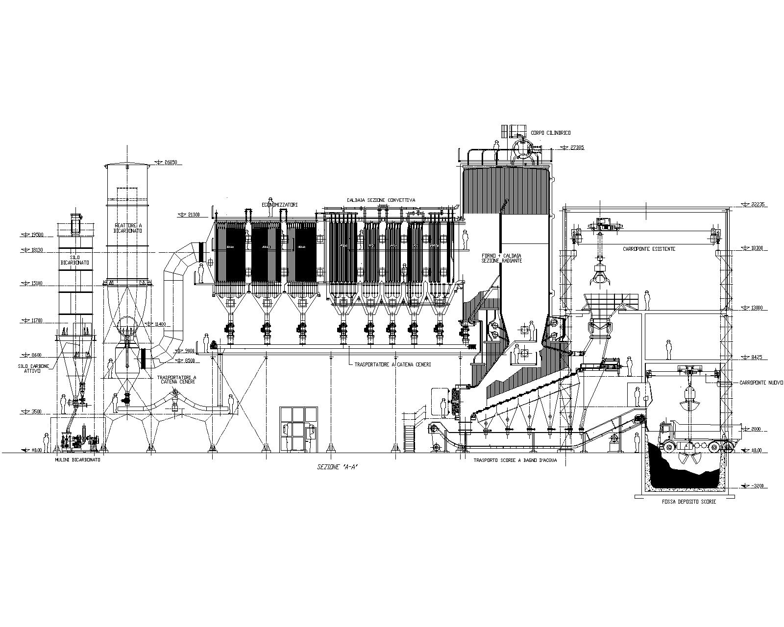
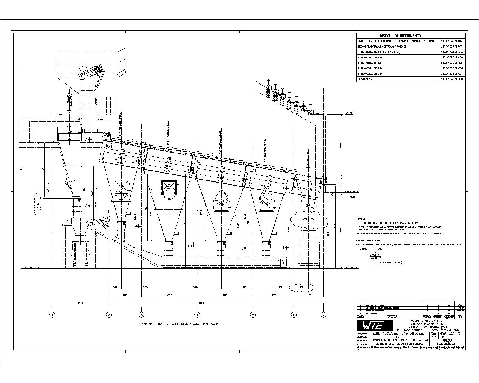
The modelling and simulation of the furnace-boiler allows a detailed investigation of the behavior of the system. Proprietary mathematical models have been developed, to optimize the design of the system, and identify critical issues that can compromise the efficiency of the system, increase the environmental impact of operations, or damage the equipment.
Amongst the elements analyzed:
- thermodynamic equilibrium of the combustion process
- geometry of the combustion chamber
- relation between the heat exchanged through furnace walls, and the values of the parameters defining the combustion process
- thermal exchange in the first sections of the boiler
- temperature of combustion air (primary and secondary)
- flame temperature
- the relation between residence time and gas temperature
- Oxygen content and presence of pollutants in the fumes
- Formation of macro and micro pollutants
- Amount of fumes to be recirculated in the system
Slideshow


Highlights


Tell us about your next project
We love facing new challenges, discussing new ideas and envisaging new projects.
Feel free to contact us: we will be glad to exchange opinions, and to figure out how we can be of further help.